Table Of ContentUser's Guide
SBAU307A–December2017–RevisedMarch2018
Precision Labs SAR ADC EVM
This user's guide describes the characteristics and use of the Precision Labs SAR ADC EVM. The
evaluation module (EVM) is designed to as a companion to the TI Precision Labs-ADCs training series
and is referred to as the PLABS-SAR-EVM-PDK throughout this document. This hardware allows
engineers to perform experiments on general data converter topics such as ADC input drive, reference
drive, amplifier selection, power consumption, and aliasing. This user's guide provides information
regarding the operation and theory behind the sub-circuits on the EVM, as well as an overview of the
requiredsoftware.
USB Cable
PLABS-SAR-EVM
PHI-EVM
(Digital Controler)
SMA
Cable
USB Cable
PSI-EVM
(Signal Source)
10 Coupon Cards
Different Amplifier
Configurations
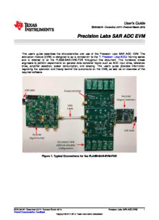
Figure1.TypicalConnectionsforthePLABS-SAR-EVM-PDK
SBAU307A–December2017–RevisedMarch2018 PrecisionLabsSARADCEVM 1
SubmitDocumentationFeedback
Copyright©2017–2018,TexasInstrumentsIncorporated
www.ti.com
ThefollowingrelateddocumentsareavailablethroughtheTexasInstrumentswebsite.
Table1.RelatedDocumentation
Device LiteratureNumber
ADS1220 SBAS501
ADS7042 SBAS608
ADS8860 SBAS569
INA326 SBOS222
LPV811 SNOSD33
OPA316 SBOS703
OPA320 SBOS513
OPA333 SBOS351
REF5050 SBOS410
REF6050 SBOS708
TLV313 SBOS753
Contents
1 Introduction................................................................................................................... 4
2 EVMInitialSetup ............................................................................................................ 4
3 Plug-InAmplifierCouponBoards ....................................................................................... 15
4 EVMGraphicalUserInterface(GUI)SoftwareInstallation........................................................... 17
5 BoardLayout................................................................................................................ 29
6 SchematicandBillofMaterials........................................................................................... 33
ListofFigures
1 TypicalConnectionsforthePLABS-SAR-EVM-PDK................................................................... 1
2 OverviewofFeaturesonCH1andCH2.................................................................................. 5
3 AmplifierandADCInput(CH1andCH2)................................................................................. 6
4 VoltageReferenceandJumper-SelectedVoltageDivider(CH1andCH2).......................................... 6
5 JumperPositionforaDCInputof0.1VonCH1andCH2............................................................ 7
6 JumperPositionforanACInputonCH1andCH2..................................................................... 7
7 PowerSubsection(CH1andCH2)........................................................................................ 8
8 ConnectiontothePHIControllerandEEPROM........................................................................ 9
9 OverviewofFeaturesonCH3............................................................................................ 10
10 AmplifierandADCInput(CH3)........................................................................................... 11
11 INACurrentMonitor(CH3)................................................................................................ 12
12 Power,ShuntResistors,andRangeSelectionforCH3 .............................................................. 13
13 DCorACInput(CH3)..................................................................................................... 14
14 CouponCardLayout....................................................................................................... 15
15 InstallingaCouponCard.................................................................................................. 15
16 PLABSToolkitLink ........................................................................................................ 17
17 ApplicationsAgreement .................................................................................................. 18
18 PlabsToolkitDialogBox.................................................................................................. 19
19 Software Installation....................................................................................................... 20
20 PlabsToolkitPrompt ...................................................................................................... 21
21 DefaultPLABS-SAR-EVMGUIDisplay ................................................................................ 21
22 PSIControls:UnconnectedPSIHardware............................................................................. 22
23 PSIControls:ReadytoGenerateanInputSignal .................................................................... 23
24 TimeDomainDisplay...................................................................................................... 24
25 SpectralAnalysisDisplay................................................................................................. 25
2 PrecisionLabsSARADCEVM SBAU307A–December2017–RevisedMarch2018
SubmitDocumentationFeedback
Copyright©2017–2018,TexasInstrumentsIncorporated
www.ti.com
26 Histogram Analysis......................................................................................................... 26
27 RegisterMapConfiguration .............................................................................................. 27
28 PowerScalingResults..................................................................................................... 28
29 PCBTopLayer............................................................................................................. 29
30 Bottom Layer................................................................................................................ 30
31 Ground Layer............................................................................................................... 31
32 Power Layer ................................................................................................................ 32
33 Page1:Channel1......................................................................................................... 33
34 Page2:Channel2......................................................................................................... 34
35 Page3:Channel1and2Power......................................................................................... 35
36 Page4:Channel3......................................................................................................... 36
37 Page5:Channel3Current-ShuntAmplifiersandADC............................................................... 37
38 Page6:Channel3LDOandShuntResistors ......................................................................... 38
39 Page7:Hardware.......................................................................................................... 39
40 OPA320GoodFilter1..................................................................................................... 40
41 OPA320BadFilter......................................................................................................... 40
42 OPA333LowBandwidth.................................................................................................. 40
43 OPA316Crossover........................................................................................................ 41
44 OPA320Noise1 ........................................................................................................... 41
45 Sallen-Key Filter............................................................................................................ 41
46 TLV313LowPower........................................................................................................ 42
47 LPV811Nanopower ....................................................................................................... 42
48 OPA320Noise2 ........................................................................................................... 42
49 OPA320GoodFilter2..................................................................................................... 43
ListofTables
1 RelatedDocumentation..................................................................................................... 2
2 HardwareIncludedinthePLABS-SAR-EVM-PDK...................................................................... 4
3 CouponCardDescriptions................................................................................................ 16
4 BillofMaterialsfortheSAR-ADC-EVMMotherboard................................................................. 44
5 BillofMaterialsfortheSAR-ADC-EVMCouponBoards.............................................................. 47
Trademarks
Alltrademarksaretheproperty oftheirrespectiveowners.
SBAU307A–December2017–RevisedMarch2018 PrecisionLabsSARADCEVM 3
SubmitDocumentationFeedback
Copyright©2017–2018,TexasInstrumentsIncorporated
Introduction www.ti.com
1 Introduction
ThePLABS-SAR-EVM-PDK isanevaluationmodule(EVM)kitcontainingasignalgenerator,ananalog-
to-digital converter(ADC)board,plug-inamplifiercards,andadigitalcontroller.Thiskitisintended to be
usedinconjunctionwiththeTIPrecisionLabs-ADCstraining series.
1.1 Features
ThePLABS-SAR-EVM-PDK includesthefollowingfeatures:
• Threesuccessive-approximationregister(SAR)ADCsub-circuitscomprisedoftheADS8860 and
REF5050,theADS8860andREF6050,andtheADS7042.
• Tenplug-inDIPadapterboardscontainingdifferent amplifierconfigurations.
• Jumper-selectableDCinputvoltages(0.1V,1V,2V,and5V).
• Jumper-selectableinput(DCorAC).
• Jumper-selectablecurrentmeasurementrangesfor theopampandADC.
• PoweredoverasingleUSBcable.
2 EVM Initial Setup
TypicalconnectionforthePLABS-SAR-EVM-PDKaregiveninFigure1.Theincludedhardwareforthis
EVM kitisgiveninTable2.
2.1 Included Hardware
Table2liststheincludedhardwarewiththisEVM.
Table2.HardwareIncludedinthePLABS-SAR-EVM-PDK
Item Quantity Description
ThisPCBcontainsthreedifferentADCconfigurationsandallowsdifferentamplifier
PLABS-SAR-EVM 1 driverstobetestedusingplug-inamplifiercouponboards.ThePCBisintendedasa
companiontoTIPrecisionLabs-ADCstrainingseriesforhands-onexperiments.
ThisPCBisthedigitalcontrollerusedtocommunicatewiththeADCsonthePLABS-
PHI-EVM 1
SAR-EVM-PDK.
ThisPCBistheistheprecisionsignalsourceusedtogeneratetestsignalsfor
PSI-EVM 1
precisionlabsexperiments.
USBcable 2 UsedtocommunicatewiththePHI-EVMandthePSI-EVM.
SMAcable 1 Usedtoconnectthesignalgenerator(PHI-EVM)tothePLABS-SAR-EVM-PDK.
OPA320goodfilter 1 DemonstratesperformanceontheADS8860.
OPA320badfilter 1 Demonstratespoorcomponentselection.
OPA333lowbandwidth 1 Demonstratespoorcomponentselection.
OPA316crossover 1 Demonstratescrossoverdistortion.
OPA320noise1 1 Demonstratesnoisemeasurement.
Sallenkeyfilter 1 Demonstratesanantialiasingfilter.
TLV313lowpower 1 Demonstrateslowpoweramplifierdriverperformance.
LPV811nanopower 1 Demonstrateslowpoweramplifierdriverperformance.
OPA320noise2 1 Demonstratesnoisemeasurement.
OPA320goodfilter2 1 DemonstratesperformanceontheADS7042.
4 PrecisionLabsSARADCEVM SBAU307A–December2017–RevisedMarch2018
SubmitDocumentationFeedback
Copyright©2017–2018,TexasInstrumentsIncorporated
www.ti.com EVMInitialSetup
2.2 Channel 1 and 2 Operation
Figure2 showsthefeaturesonchannel1andchannel2(CH1andCH2,respectively)ofthePLABS-SAR-
EVM.Thedesignofthesetwochannelsisverysimilar.Theonlydifferenceisthat channel1usesthe
REF5050andchannel2usestheREF6050.TheREF6050containsawidebandwidthbuffer andthus
showsbetterperformancethantheREF5050.Thegoalistoshowtheimpactthat referencebufferinghas
onperformance.BothchannelshaveanSubMiniatureversionA(SMA)input connectorfor theACinput
andbothchannelsshareaprecisionDCsource. ThethreeLEDindicatorsaresharedbetweenthe two
channelsandareagoodquickchecktodetermineiftheboardispowered.Eachchannelhasit'sown
connectortothePHIdigitalcontroller,andthesoftwareusedfor eachchannelisidentical.
Test points for key Connector to digital
signals and supplies controller PHI for CH1
Texas
Instruments
GND
Precision Labs
PLABS-SAR-EVM
AC input CH1 VREF5050 PWR_3.3V PWR_5.2V
AVDDDVDD
Input
SAR ADS
5.2V IN-
ADS8860
VIN IN+ S2
S1 RSH
GND GND VNI COPM REG
Input CH1 GND GND CSH
CDAC PHI_CH1
S1
GND REF5050 GND
AC or DC DAQ Channel 1
Led power
input selection
AC_IN DC_IN indicators
4.9V
3.5V PWR_5.2V PWR_3.3V PWR_PHI
DC input for 2.5V
0.1V SDI
CH1 and CH2
AVDDDVDD CVST
SAR ADS SCLK
5.2V IN- ADS8860
S2 SDO
VIN IN+ VI S1 RSH COM REG
GND GND N CSH P
Input CH2 GND GND CDAC
Input
AC input CH1 REF6050 S2 PHI_CH2
GND GND
DAQ Channel 2
Socket for
amplifier Connector to digital
controller PHI for CH2
Figure2.OverviewofFeaturesonCH1andCH2
SBAU307A–December2017–RevisedMarch2018 PrecisionLabsSARADCEVM 5
SubmitDocumentationFeedback
Copyright©2017–2018,TexasInstrumentsIncorporated
EVMInitialSetup www.ti.com
2.2.1 AmplifierandADCInput(CH1andCH2)
Figure3 showstheACinput(inputCH1)connectedtotheamplifierinput onthecouponboard.The output
ofthecouponboardconnectstotheADS8860input.Bothchannel1and2havethissameconfiguration.
TheDCinputsignalisgeneratedbyareferenceandvoltagedivider.
Figure3.AmplifierandADCInput(CH1andCH2)
2.2.2 JumpersandReference(CH1andCH2)
Figure4 showshowtheprecisionDCinput signalsaregeneratedusingareferencewithajumper-
selectedvoltagedivider.DependingonthepositionofthejumperintheDCoptionsthedivideroutputis
0.1V,2.5V,3.5V,or4.9V.Ifthejumperisinthepositionshown, theoutputvoltageis0.1V.The
amplifier U6bufferstheprecisionDCsignal.U8isthereferencefor channel1.
Figure4.VoltageReferenceandJumper-SelectedVoltageDivider(CH1andCH2)
6 PrecisionLabsSARADCEVM SBAU307A–December2017–RevisedMarch2018
SubmitDocumentationFeedback
Copyright©2017–2018,TexasInstrumentsIncorporated
www.ti.com EVMInitialSetup
Figure5 showsthejumpersettingsfora0.1-VDCinput.WhenusingDCinput mode,disconnecttheinput
signalfromtheSMAconnector(inputCH2).
Connect DC input
from Reference
AC_IN DC_IN
4.9V
3.5V PWR_5.2V PWR_3.3V PWR_PHI
Apply 0.1V to 2.5V
0.1V SDI
amplifier input
AVDDDVDD CVST
SAR ADS SCLK
5.2V IN- ADS8860
S2 SDO
VIN IN+ VI S1 RSH COM REG
GND GND N CSH P
Input CH2 GND GND CDAC
Disconnect AC
Input
S2 PHI_CH2
Signals when REF6050
GND GND
using DC input
DAQ Channel 2
Figure5.JumperPositionforaDCInputof0.1VonCH1andCH2
Figure6 showsthejumpersettingsforanACinput.WhenusingACinput mode, theDCjumperbankis
ignored.
AC input only
connected
AC_IN DC_IN
4.9V
3.5V PWR_5.2V PWR_3.3V PWR_PHI
This jumper
2.5V
bank is ignored 0.1V SDI
in this mode. AVDDDVDD CVST
SAR ADS SCLK
5.2V IN- ADS8860
S2 SDO
VIN IN+ VI S1 RSH COM REG
GND GND N CSH P
Input CH2 GND GND CDAC
Connect AC
Input
S2 PHI_CH2
REF6050
Signals using
GND GND
SMA Connector
DAQ Channel 2
Figure6.JumperPositionforanACInputonCH1andCH2
SBAU307A–December2017–RevisedMarch2018 PrecisionLabsSARADCEVM 7
SubmitDocumentationFeedback
Copyright©2017–2018,TexasInstrumentsIncorporated
EVMInitialSetup www.ti.com
2.2.3 PowerSubsection(CH1andCh2)
ThePHI-EVMcontrollergeneratesa5.5-VsupplywiththeUSBpower andachargepump.Figure 7
showsthe connectionbetweenthe5.5-Vsupplytotwodifferent low-noise,lowdropoutregulators (LDOs).
U9generatesa5.2-VsupplyusedfortheamplifierandU11generatesthe3.3-Vsupplyusedbythe
ADS8860.
Figure7.Power Subsection(CH1andCH2)
8 PrecisionLabsSARADCEVM SBAU307A–December2017–RevisedMarch2018
SubmitDocumentationFeedback
Copyright©2017–2018,TexasInstrumentsIncorporated
www.ti.com EVMInitialSetup
2.2.4 ConnectiontothePHIControlerandEEPROM
Figure8 showstheconnectorusedtointerfacethedigitalcontroller (PHI-EVM) andthePLABS-SAR-
EVM.TheschematicalsoshowsanEEPROM that isusedfor boardidentification.
Figure8.ConnectiontothePHIControllerandEEPROM
SBAU307A–December2017–RevisedMarch2018 PrecisionLabsSARADCEVM 9
SubmitDocumentationFeedback
Copyright©2017–2018,TexasInstrumentsIncorporated
EVMInitialSetup www.ti.com
2.3 Channel 3 Operation
Figure9 showsthefeaturesonCH3ofthePLABS-SAR-EVM.ThischannelallowsDCorACsignalsto be
appliedto theADS7042.Plug-inamplifiercouponcardsareusedtoexperimentwithdifferent amplifier
drivecircuits.Thechannelalsoprovidescurrent measurementcircuitryfor measuringtheanalogsupply
current,digital supplycurrent,andamplifier supplycurrent.Thecurrentmeasurementcircuit hasjumper-
selectedrangesforhighcurrent,lowcurrent, andcalibration.Current-shuntamplifiersandanADS1220
areusedtomeasurethecurrents.ThethreeLEDindicatorsaresharedbetweenthetwochannelsandare
agoodquickchecktodetermineiftheboardispowered.
Led power
indicators Connector to digital
controller PHI for CH3
PWR_5.2V PWR_3.3V PWR_PHI
2.5V
AC or DC 1.5V LOW LOW LOW
input selection 1.0V
CAL CAL CAL
0.1V
HIGH HIGH HIGH
DC input for DC_IN
Current Current Current
CH1 and CH2 AVDD-AMP AVDD-ADC DVDD-AMP
AC_IN
VIAMP VIA VID
5.2V IN- AVDD_AMP AVDD DVDD
VIN IN+ A A A
GND GND
GND GND VIN SAR ADC
AC input CH4 Input ADS7042 S3 PHI_CH3
GND GND
Power Scaling Channel 3
Test points for key Socket for
signals and supplies amplifier
Figure9.OverviewofFeaturesonCH3
10 PrecisionLabsSARADCEVM SBAU307A–December2017–RevisedMarch2018
SubmitDocumentationFeedback
Copyright©2017–2018,TexasInstrumentsIncorporated
Description:This user's guide describes the characteristics and use of the Precision Labs and is referred to as the PLABS-SAR-EVM-PDK throughout this document. The system is intentionally in a noninverting topology with a non zero-

