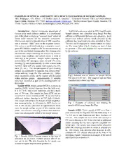
Download NASA Technical Reports Server (NTRS) 20130004212: Examples of Optical Assessment of Surface Cleanliness of Genesis Samples PDF Free - Full Version
Download NASA Technical Reports Server (NTRS) 20130004212: Examples of Optical Assessment of Surface Cleanliness of Genesis Samples by NASA Technical Reports Server (NTRS) in PDF format completely FREE. No registration required, no payment needed. Get instant access to this valuable resource on PDFdrive.to!
About NASA Technical Reports Server (NTRS) 20130004212: Examples of Optical Assessment of Surface Cleanliness of Genesis Samples
No description available for this book.
Detailed Information
| Author: | NASA Technical Reports Server (NTRS) |
|---|---|
| Language: | English |
| File Size: | 0.07 |
| Format: | |
| Price: | FREE |
Safe & Secure Download - No registration required
Why Choose PDFdrive for Your Free NASA Technical Reports Server (NTRS) 20130004212: Examples of Optical Assessment of Surface Cleanliness of Genesis Samples Download?
- 100% Free: No hidden fees or subscriptions required for one book every day.
- No Registration: Immediate access is available without creating accounts for one book every day.
- Safe and Secure: Clean downloads without malware or viruses
- Multiple Formats: PDF, MOBI, Mpub,... optimized for all devices
- Educational Resource: Supporting knowledge sharing and learning
Frequently Asked Questions
Is it really free to download NASA Technical Reports Server (NTRS) 20130004212: Examples of Optical Assessment of Surface Cleanliness of Genesis Samples PDF?
Yes, on https://PDFdrive.to you can download NASA Technical Reports Server (NTRS) 20130004212: Examples of Optical Assessment of Surface Cleanliness of Genesis Samples by NASA Technical Reports Server (NTRS) completely free. We don't require any payment, subscription, or registration to access this PDF file. For 3 books every day.
How can I read NASA Technical Reports Server (NTRS) 20130004212: Examples of Optical Assessment of Surface Cleanliness of Genesis Samples on my mobile device?
After downloading NASA Technical Reports Server (NTRS) 20130004212: Examples of Optical Assessment of Surface Cleanliness of Genesis Samples PDF, you can open it with any PDF reader app on your phone or tablet. We recommend using Adobe Acrobat Reader, Apple Books, or Google Play Books for the best reading experience.
Is this the full version of NASA Technical Reports Server (NTRS) 20130004212: Examples of Optical Assessment of Surface Cleanliness of Genesis Samples?
Yes, this is the complete PDF version of NASA Technical Reports Server (NTRS) 20130004212: Examples of Optical Assessment of Surface Cleanliness of Genesis Samples by NASA Technical Reports Server (NTRS). You will be able to read the entire content as in the printed version without missing any pages.
Is it legal to download NASA Technical Reports Server (NTRS) 20130004212: Examples of Optical Assessment of Surface Cleanliness of Genesis Samples PDF for free?
https://PDFdrive.to provides links to free educational resources available online. We do not store any files on our servers. Please be aware of copyright laws in your country before downloading.
The materials shared are intended for research, educational, and personal use in accordance with fair use principles.

