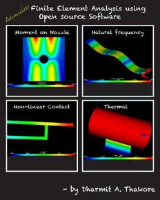
Table Of ContentFinite Element Analysis using
e
t
a Open source Software
i
d
e
m
r
e
t
n
I
Moment on Nozzle Natural frequency
Non-linear Contact Thermal
- by Dharmit A. Thakore
Intermediate Finite Element Analysis
with
Open Source Software
First Edition
Intermediate Finite Element Analysis with
Open Source Software
First Edition
Dharmit Thakore, CPEng, RPEQ
Moonish Ent. Pty. Ltd.
Brisbane, QLD, Australia
Moonish Enterprises Pty Ltd
GPO Box 1299, Brisbane, QLD 4001, Australia
2014
Credits and Copyright
Written by: Dharmit Thakore
[email protected]
Publisher: Moonish Ent. Pty. Ltd
[email protected]
http://engineering.moonish.biz
Graphic Design / Layout: Lomesha Thakore
[email protected]
Edition 1 ©2014 Dharmit Thakore
No part of this publication may be reproduced, stored or transmitted in any form or by any means, electronic,
mechanical or otherwise, without prior written consent from the publisher, except for the inclusion of brief
quotations in a review. You may store the pdf on your computer and backups. You may print one copy of this
book for your own personal use.
Disclaimer: The information contained in this book is based on the author’s experience, knowledge and
opinions. The author and publisher will not be held liable for the use or misuse of the information in this book.
To
My wife,
Our beloved son
&
Open Source Software
About the Author
Dharmit Thakore is the Director of Moonish Enterprises Pty Ltd at Brisbane, Queensland, Australia. He
practices as a Mechanical / Piping Engineer in Queensland. He received his Bachelor’s degree from Birla
Vishwakarma Mahavidhyalaya, Vallabh Vidhyanagar, Gujarat, India which was affiliated with Sardar Patel
University. He started his engineering career as a young Graduate in Larsen & Toubro – Sargent & Lundy,
Vadodara. He came to Australia for further studies and settled here. He received his Registered Professional
Engineer in Queensland (RPEQ) recognition early in his career and subsequently obtained his Chartered
Professional Engineer (CPEng) as a Mechanical / Piping Engineer.
Dharmit has broad interests, which include finite element analysis, design, optimization and Open Source
software. He is a member of ASME, Engineers Australia and Board of Professional Engineers in Queensland.
Table of Contents
Foreword xiii
This book is written for xiii
This book is not written for xiii
What are the steps in Finite Element Analysis xv
Study Cases xvii
Parametric Modelling in Salome for Geometry and Mesh generation xvii
Combining element types in a single FE Analysis xvii
Non Linear Material Analysis xvii
Contact FE analysis xvii
Modal Analysis xvii
Thermal Analysis xviii
Parametric Modelling of a Pressure Vessel Geometry 1
Step 1: Description of the problem 2
Step 2: Input values for the FE analysis 2
Step 3: Parametric Modelling by direct editing of .py file 2
Step 4: Meshing using Notebook 30
Change Parameter in Notebook 34
Summary 36
Adding Moments to a face in 3D model 37
Step 1: Description of the problem 38
Step 2: Input values for the FE analysis 38
Step 3 and 4: Generating Geometry by Parametric Modelling and editing mesh 38
Step 5, 6, 7, 8 and 9: Reusing .comm file from Case9 and editing it 44
Step 10: Run the analysis 49
Step 11: Post Processing of the Results 50
Summary 55
Combining Element types in a single FE Analysis 56
Step 1: Purpose of the FE Analysis / Description of the problem 57
Step 2: Input values for the FE analysis 57
Step 3: Model Geometry 57
Step 4: Meshing Geometry 66
Step 5, 6, 7, 8 and 9: Generating command file by hand 69
Step 10: Run the analysis 73
Step 11: Post Processing of the Results 75
Summary 80
Non-Linear Material FE Analysis 81
Step 1: Purpose of the FE Analysis / Description of the problem 82
Step 2: Input values for the FE analysis 82
Step 3: Model Geometry 83
Step 4: Meshing Geometry 85
Step 5, 6, 7, 8 and 9: Modifying comm file created by Efficient 88
Step 10: Run the analysis 96
Step 11: Post Processing of the Results 102
Summary 106
Non-Linear Material – Real Curve FE Analysis 108
Step 1: Purpose of the FE Analysis / Description of the problem 109
Step 2: Input values for the FE analysis 109
Step 3: Model Geometry 110
Step 4: Meshing Geometry 110
Step 5, 6, 7, 8 and 9: Modifying comm file created by Efficient 110
Step 10: Run the analysis 114
Step 11: Post Processing of the Results 114
Summary 116
Non-Linear FE Analysis with Contact 117
Step 1: Purpose of the FE Analysis / Description of the problem 118
Step 2: Input values for the FE analysis 118
Step 3: Model Geometry 119
Step 4: Meshing Geometry 123
Step 5, 6, 7, 8 and 9: Modifying comm file created by Efficient 126
Step 10: Run the analysis 134
Step 11: Post Processing of the Results 139
Summary 142
Non-Linear FE Analysis with Contact and Non-Linear Material 143
Step 1: Purpose of the FE Analysis / Description of the problem 144
Step 2: Input values for the FE analysis 144
Step 3: Model Geometry 145
Step 4: Meshing Geometry 145
Step 5, 6, 7, 8 and 9: Modifying comm file created by Efficient 145
Step 10: Run the analysis 148
Step 11: Post Processing of the Results 149
Summary 150
FE Analysis of 3D Plate for Mode Shapes 151
Step 1: Purpose of the FE Analysis / Description of the problem 152
Step 2: Input values for the FE analysis 152
Step 3: Model Geometry 154
Step 4: Meshing Geometry 156
Step 5, 6, 7, 8 and 9: Creating command file by Wizard 159
Step 10: Run the analysis 162
Step 11: Post Processing of the Results 162
Summary 167
FE Analysis of 1D Beam for Mode Shapes 168

