Download fingerprint based driving license management system PDF Free - Full Version
Download fingerprint based driving license management system by in PDF format completely FREE. No registration required, no payment needed. Get instant access to this valuable resource on PDFdrive.to!
About fingerprint based driving license management system
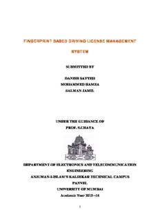
Anjuman-I-Islam's Kalsekar Technical Campus Panvel during the academic year 20 – 20. Internal guide . Reference. 70 the result of chemical reaction or evaporation of solvent. Thermal . The device is manufactured using Atmel's high- . Since Simula--‐type objects are implemented in C++, Java.
Detailed Information
| Author: | Unknown |
|---|---|
| Publication Year: | 2016 |
| Pages: | 81 |
| Language: | English |
| File Size: | 8.81 |
| Format: | |
| Price: | FREE |
Safe & Secure Download - No registration required
Why Choose PDFdrive for Your Free fingerprint based driving license management system Download?
- 100% Free: No hidden fees or subscriptions required for one book every day.
- No Registration: Immediate access is available without creating accounts for one book every day.
- Safe and Secure: Clean downloads without malware or viruses
- Multiple Formats: PDF, MOBI, Mpub,... optimized for all devices
- Educational Resource: Supporting knowledge sharing and learning
Frequently Asked Questions
Is it really free to download fingerprint based driving license management system PDF?
Yes, on https://PDFdrive.to you can download fingerprint based driving license management system by completely free. We don't require any payment, subscription, or registration to access this PDF file. For 3 books every day.
How can I read fingerprint based driving license management system on my mobile device?
After downloading fingerprint based driving license management system PDF, you can open it with any PDF reader app on your phone or tablet. We recommend using Adobe Acrobat Reader, Apple Books, or Google Play Books for the best reading experience.
Is this the full version of fingerprint based driving license management system?
Yes, this is the complete PDF version of fingerprint based driving license management system by Unknow. You will be able to read the entire content as in the printed version without missing any pages.
Is it legal to download fingerprint based driving license management system PDF for free?
https://PDFdrive.to provides links to free educational resources available online. We do not store any files on our servers. Please be aware of copyright laws in your country before downloading.
The materials shared are intended for research, educational, and personal use in accordance with fair use principles.

