ebook img

Single Impulse Deorbit (short paper) PDF

4 Pages·1966·0.134 MB·English
by  
Save to my drive
Quick download
Download
Most books are stored in the elastic cloud where traffic is expensive. For this reason, we have a limit on daily download.

Preview Single Impulse Deorbit (short paper)

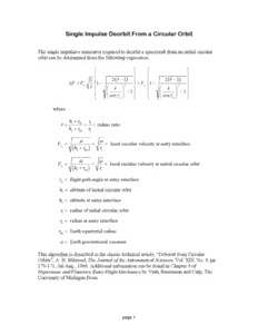
Single Impulse Deorbit From a Circular Orbit The single impulsive maneuver required to deorbit a spacecraft from an initial circular orbit can be determined from the following expression         1  2(r(cid:4)−1)   2(r(cid:4)−1)  ∆V =V 1− =V 1−  ce r(cid:4)   r(cid:4) 2  ci   r(cid:4) 2  −1 −1         cosγ cosγ   e     e   where h +r r r(cid:4) = i eq = i = radius ratio h +r r e eq e µ µ V = = = local circular velocity at entry interface ce (h +r ) r e eq e µ µ V = = = local circular velocity at initial circular orbit ci (h +r ) r i eq i γ = flight path angle at entry interface e h = altitude of initial circular orbit i h = altitude at entry interface e r = radius of initial circular orbit i r = radius at entry interface e r = Earth equatorial radius eq µ= Earth gravitational constant This algorithm is described in the classic technical article, “Deboost from Circular Orbits”, A. H. Milstead, The Journal of the Astronautical Sciences, Vol. XIII, No. 4, pp. 170-171, Jul-Aug., 1966. Additional information can be found in Chapter 5 of Hypersonic and Planetary Entry Flight Mechanics by Vinh, Busemann and Culp, The University of Michigan Press. page 1 The true anomaly on the deorbit trajectory at the entry interface θ can be determined e from the following two equations: r(cid:5) a (1−e2) sinθ = d d e e µ d a (1−e2) 1 cosθ = d d − e e r e d e d and the following four quadrant inverse tangent operation θ = tan−1(sinθ,cosθ) e e e where e = eccentricity of deorbit trajectory d a = semimajor axis of deorbit trajectory d µ2a r −r2 −a2(1−e2) r(cid:5)=−  d e e d d  a r2 d e The time of flight between perigee of the deorbit trajectory and the entry true anomaly θ e is given by τ   1−e θ  e 1−e2 sinθ  t(θ)= 2tan−1 d tan e− d d e e 2π  1+ed 2  1+ed cosθe  In this equation τ is the orbital period of the deorbit trajectory and is equal to 2π a3 µ. d Therefore, the flight time between the deorbit impulse and entry interface is given by τ ∆t =t(θ)−t(180(cid:68))=t(θ)− e e 2 Finally, the orbital speed at the entry interface V can be determined from e 2µ µ V = − e r a e d page 2 The following is a graphics display of the single impulsive ∆V required to deorbit from a range of circular Earth orbit altitudes and several entry interface flight path angles. The entry interface altitude for this example is 400,000 feet. Deorbit Delta-V versus Initial Circular Orbit Altitude 900 and Flight Path Angle at Entry Interface 800 altitude at entry interface = 400,000 feet 700 s) V (fp 600 aftli gehntt rpya itnht earnfagclee a- elt -20 D orbit 500 alt = 190.8 nm -1.50 De ∆v = 444.5 fps -10 400 alt = 158.9 nm ∆v = 334.1 fps 300 alt = 127.6 nm ∆v = 223.2 fps impulsive maneuver 200 50 100 150 200 250 300 350 Initial Circular Orbit Altitude (nm) This plot is also labeled with the optimum deorbit altitude and corresponding ∆V for a given flight path angle at the entry interface. An examination of the following plot of the eccentricity of the deorbit trajectory reveals why these minima exist. Eccentricity of Deorbit Trajectory versus Initial Circular Orbit Altitude and Flight Path Angle at Entry Interface 0.07 -20 0.06 ectory 0.05 altitude at entry interface = 400,000 feet aj bit tr deor 0.04 -1.50 of city ntri Ecce 0.03 0.02 -10 flight path angle impulsive maneuver at entry interface 0.01 50 100 150 200 250 300 350 Initial Circular Orbit Altitude (nm) page 3 The next two plots illustrate the behavior of the impulse-to-entry interface mission time and speed at the entry interface. Impulse-to-Entry Time versus Initial Circular Orbit Altitude and Flight Path Angle at Entry Interface 40 -10 -1.50 -20 30 flight path angle at entry interface n) mi y ( ntr E o V t 20 ∆ m o me fr altitude at entry interface = 400,000 feet Ti 10 impulsive maneuver 0 50 100 150 200 250 300 350 Initial Circular Orbit Altitude (nm) Entry Speed versus Initial Circular Orbit Altitude 26400 and Flight Path Angle at Entry Interface 26000 s) p e (f c a erf nt y I 25600 ntr -10 E at d e pe altitude at entry interface = 400,000 feet S -1.50 25200 -20 flight path angle impulsive maneuver at entry interface 24800 50 100 150 200 250 300 350 Initial Circular Orbit Altitude (nm) page 4

See more

The list of books you might like

Most books are stored in the elastic cloud where traffic is expensive. For this reason, we have a limit on daily download.