NASA Technical Reports Server (NTRS) 20110016551: Compact Optoelectronic Compass PDF
Preview NASA Technical Reports Server (NTRS) 20110016551: Compact Optoelectronic Compass
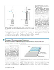
greater tip force for a given degree of differential expansion or contraction of x x the bonded layers. Taking all of these effects into ac- Backplate count, the cantilever-beam equations d d show that Fb would be approximately F Fb inversely proportional to d1/2for dless than a calculable amount, denoted the transition displacement (dt). For d < L* dt, part of the strip would be pressed against the backplate. Therefore, the L L force Fbwould be very large for dat or near zero and would decrease as d in- creases toward dt. At d> dt, none of the strip would be pressed against the y y backplate and Fb would equal the tip force F of the corresponding ordinary bending actuator. The advantage of the proposal is that a backed bending actuator could be made long to obtain large displacement when it encoun- ORDINARY BENDING BACKED BENDING tered little resistance but it could also ACTUATOR ACTUATOR exert a large zero-displacement force, so that it could more easily start the A Backed Bending Actuatorwould resemble an ordinary bending actuator except that it would in- movement of a large mass, throw a me- clude a backplate that would enable a large displacement together with a large force at small dis- placements. chanical switch, or release a stuck mechanism. expansion or contraction of the bonded placement of the tip could be sufficient This work was done by Robert C. Costen layers. The bending, displacement, and to push part of the strip against the and Ji Su of Langley Research Center. tip force of the backed bending actua- backplate; in such a condition, the can- Further information is contained in a TSP tor are calculated similarly, except that tilever beam would be effectively short- (see page 1) it is necessary to account for the fact ened (length L*) and thereby stiffened LAR-16441 that the force Fb that resists the dis- and, hence, made capable of exerting a Compact Optoelectronic Compass The axis of rotation of the Earth is estimated from the changing direction to the Sun. NASA’s Jet Propulsion Laboratory, Pasadena, California A compact optoelectronic sensor unit measures the apparent motion of the Mask Containing Sun across the sky. The data acquired by Pinholes this chip are processed in an external processor to estimate the relative orien- tation of the axis of rotation of the Earth. Hence, the combination of this chip and Spacer the external processor finds the direc- tion of true North relative to the chip: in Active-Pixel Sensor other words, the combination acts as a (Hidden Behind Mask and Spacer) solar compass. If the compass is further combined with a clock, then the combi- nation can be used to establish a three- Integrated-Circuit Chip axis inertial coordinate system. If, in ad- dition, an auxiliary sensor measures the local vertical direction, then the result- A Compact Multiple-Pinhole Camerasenses the apparent position of the Sun and its apparent motion ing system can determine the geographic across the sky. position. This chip and the software used in the craft” (NPO-30867) elsewhere in this issue ing a micromachined mask containing a processor are based mostly on the same of NASA Tech Briefs. Like the unit de- rectangular array of microscopic pinholes design and operation as those of the unit scribed in that article, this unit includes a mounted a short distance in front of an described in “Micro Sun Sensor for Space- small multiple-pinhole camera compris- image detector of the active-pixel sensor NASA Tech Briefs, January 2004 7 (APS) type (see figure). Further as in the tion of the Earth during an observation North (within tens of degrees) in an other unit, the digitized output of the APS interval (during which the Sun sensor observation time of about ten minutes. in this chip is processed to compute the must remain stationary with respect to As expected, the accuracy was found to centroids of the pinhole Sun images on the Earth). The apparent path of the increase with observation time: after a the APS. Then the direction to the Sun, Sun across the sky is projected on a few hours, the estimated direction of relative to the compass chip, is computed sphere. The axis of rotation of the the rotation axis becomes accurate to from the positions of the centroids (just Earth lies at the center of the projected within a small fraction of a degree. like a sundial). circle on the sphere surface. Hence, This work was done by Carl Christian In the operation of this chip, one is true North (not magnetic North), rela- Liebe of Caltech for NASA’s Jet Propul- interested not only in the instanta- tive to the chip, can be estimated from sion Laboratory. Further information is neous direction to the Sun but also in paths of the Sun images across the APS. contained in a TSP (see page 1) the apparent path traced out by the di- In a test, this solar compass has been NPO-30872 rection to the Sun as a result of rota- found to yield a coarse estimate of the 8 NASA Tech Briefs, January 2004
