NASA Technical Reports Server (NTRS) 20090008427: Truncation Depth Rule-of-Thumb for Convolutional Codes PDF
Preview NASA Technical Reports Server (NTRS) 20090008427: Truncation Depth Rule-of-Thumb for Convolutional Codes
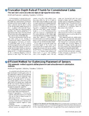
Truncation Depth Rule-of-Thumb for Convolutional Codes The new rule is more accurate and tight at high signal-to-noise ratios. NASA’s Jet Propulsion Laboratory, Pasadena, California In this innovation, it is shown that a com- code is r= log (M)/nbits/symbol. A ran- codes are represented with the same 2 monly used rule of thumb (that the trunca- dom trellis code is an (M, ν, n) trellis in number of states, with k/k stages of the 1 tion depth of a convolutional code should which each channel symbol on each edge mother code corresponding to 1 stage of be five times the memory length, m, of the is chosen randomly and independently ac- the daughter code. The required trunca- code) is accurate only for rate 1/2 codes. cording to some distribution p. When M= tion depth on the daughter code trellis In fact, the truncation depth should be 2.5 qkthe (M, ν, n) trellis corresponds to a rate corresponds to a truncation depth on m/(1 – r), where ris the code rate. The ac- log(q)k/n nonsystematic convolutional the mother code trellis of 2 curacy of this new rule is demonstrated by code over GF(q) with k equal constraint 1> ν /(1 – r) 1 tabulating the distance properties of a lengths ν = ν, 1 < i< k. The memory of this i.e., the truncation depth on the mother i large set of known codes. This new rule was code is m= maxν= ν. It is presumed that code goes as the memory of the mother i i derived by bounding the losses due to trun- the code is decoded via the Viterbi algo- code scaled by one minus the rate of the cation as a function of the code rate. rithm with decisions on edges of the trellis punctured code. The bound derives from a result on ran- made after a delay of T trellis stages. A With regard to particular codes, a good dom trellis codes in G.D. Forney, Jr.’s truncation error occurs when an incorrect indicator of the required truncation “Convolutional codes II: Maximum likeli- edge is chosen that would not have been depth is the path length at which all paths hood decoding,” Information and Control, chosen with an infinite truncation depth. that diverge from a particular path have vol. 25:222-266 (1974). An (M, ν) trellis is In the case of punctured codes, the accumulated the minimum distance of a trellis corresponding to a shift register of truncation depth on the mother code the code. It is shown that the new rule of length νwhere each register contains a M- trellis should be increased as the rate in- thumb provides an accurate prediction of vector and the input is an M-ary sequence creases. Punctured code can be created this depth for codes of varying rates. (the corresponding trellis contains Mv by forming (qk, ν, n) code by puncturing This work was done by Bruce Moision of states). An (M, ν, n) trellis code augments a (qk, ν , n ) mother code, where k di- Caltech for NASA’s Jet Propulsion Laboratory. 1 1 1 an (M, ν) trellis by assigning n channel vides k and ν = ν k /k. This resulting Further information is contained in a TSP 1 1 symbols to each edge. The rate of the code is the daughter code. The two (see page 1). NPO-45009 Efficient Method for Optimizing Placement of Sensors This systematic method supplants ad hoc placement and exhaustive-search optimization methods. NASA’s Jet Propulsion Laboratory, Pasadena, California A computationally efficient method has been developed to enable optimization of a x M1 the placement of sensors for the purpose of diagnosis of a complex engineering sys- Component M1 x = ab b A1 f tem (e.g., an aircraft or spacecraft). The Component M2 y = bc y method can be used both in (1) design- Component M3 z = cd M2 ing a sensor system in which the number Component M4 t = de c A2 g and positions of sensors are initially not Component A1 f = x + y M3 z known and must be determined and (2) Component A2 g = y + z adding sensors to a pre-existing system to Component A3 h = z + t d A3 h increase the diagnostic capability. t The optimal-sensor-placement problem e M4 can be summarized as involving the follow- ing concepts, issues, and subproblems: Signature Matrix (cid:129) Degree of Diagnosability— This is a con- ARR M1 M2 M3 M4 A1 A2 A3 cept for characterizing the set of faults f – ab – bc = 0 1 1 0 0 1 0 0 that can be discriminated by use of a g – bc – de = 0 0 1 1 0 0 1 0 given set of sensors. h – cd – de = 0 0 0 1 1 0 0 1 (cid:129) Minimal Sensor Set — The idea is one of f – g – ab + cd = 0 1 0 1 0 1 1 0 g – h – bc + de = 0 0 1 0 1 0 1 1 finding a minimal set of sensors that guarantees a specific degree of diag- nosability. A System of Four Multiplier and Three Adder Gatesserves as an example for illustrating the concept of ARRs and a signature matrix. In this example, there are three sensors that measure the variables f, (cid:129) Minimal-Cost Sensors— In a case in which g, and h. Each element of the matrix is 1 or 0 if the ARR listed in the row containing that element is different sensors are assigned with dif- or is not, respectively, affected by a fault in the gate listed in the column containing that element. 32 NASA Tech Briefs, January 2009
