Fisher And Paykel Smartdrive Motor 2010 PDF
Preview Fisher And Paykel Smartdrive Motor 2010
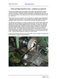
Cogen Microsystems www.cogenmicro.com Page 1 of 4 Fisher and Paykel Smartdrive motor – suitability as an alternator Two Fisher and Paykel Smartdrive washing machine motors were liberated from washing machines and tested to gauge their suitability as alternators. Apparently there are three versions of this motor – the difference being the windings. The windings have either 0.6, 0.8 or 1.0mm wire diameters. In our testing one motor had 0.6mm wire diameter whilst the other had 1.0mm wire. These motors have proven popular for use as alternators in renewable energy developments – particularly small wind turbines. We found however that there was a dearth of information available on these versatile motors, so we decided to test them and publish the results. The alternators were tested over a range of speeds and loads. A mathematical model of the alternator was then developed using regression techniques and this was used to determine performance at a wider range of speeds and loads. The results are shown in the alternator characteristic graphs below. Please note that these graphs extrapolate the characteristics well beyond what was tested (we did not test above 1300rpm for instance) so please use these with caution. At the higher power outputs the windings may also get hot (and the winding resistance will increase, altering the characteristic) – we did not test for long enough to get to steady state conditions. Note also that the sample size in testing was a grand total of one – there may well be significant variation from motor to motor. A picture of our high tech testing set up involving a lathe, lever arm, weights a multimeter and some light globes is shown in the pictures below: Cogen Microsystems www.cogenmicro.com Page 2 of 4 The model that we found to best fit our test results was: R i w i k k V * * ) * ( 2 1 − − = 2 3 2 1 * * ) * ( w k i i k k T + − = Where V= winding output voltage, rms, volts i = winding current w = alternator speed in rad/s R = winding resistance T = torque, Nm (note 1 rpm is 0.10417 rad/s) These motors are 3 phase. Our testing was performed on one winding only. Motor R ohms k1 k2 k3 0.6 wire 16.2 7.719 3.233 2.5008E-05 1.0 wire 1.33 1.102 0.0535 6.4274E-05 Cogen Microsystems www.cogenmicro.com Page 3 of 4 0.6 wire alternator - RMS voltage variation with load in Ohms (1 winding only) 0 200 400 600 800 1000 1200 1400 1600 1800 2000 0 500 1000 1500 2000 2500 speed rpm Voltage V 100 150 250 400 1000 no load 0.6 wire alternator - Output power variation with load in Ohms (1 winding only) 0 200 400 600 800 1000 1200 0 500 1000 1500 2000 2500 speed rpm Power- Watts 100 150 250 400 1000 no load 0.6 wire alternator - Efficiency variation with load in Ohms 0 20 40 60 80 100 120 0 500 1000 1500 2000 2500 speed rpm Efficiency % 100 150 250 400 1000 no load Cogen Microsystems www.cogenmicro.com Page 4 of 4 1.0 wire alternator - RMS voltage variation with load in Ohms (1 winding only) 0 50 100 150 200 250 300 0 500 1000 1500 2000 2500 speed rpm Voltage V 10 20 40 80 160 no load 1.0 wire alternator - Output power variation with load in Ohms (1 winding only) 0 200 400 600 800 1000 1200 0 500 1000 1500 2000 2500 speed rpm Power- Watts 10 20 40 80 160 no load 1.0 wire alternator - Efficiency variation with load in Ohms 0 20 40 60 80 100 120 0 500 1000 1500 2000 2500 speed rpm Efficiency % 10 20 40 80 160 no load
