energy and angle resolved ion scattering spectroscopy PDF
Preview energy and angle resolved ion scattering spectroscopy
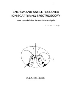
ENERGY AND ANGLE RESOLVED ION SCATTERING SPECTROSCOPY new possibilities for surface analysis INIS-mf--10804 GJ.A. HELLINGS ENERGY AND ANGLE RESOLVED ION SCATTERING SPECTROSCOPY new possibilities for surface analysis PROEFSCHRIFT TER VERKRIJGING VAN DE GRAAD VAN DOCTOR IN DE TECHNISCHE WETENSCHAPPEN AAN DE TECHNISCHE HOGESCHOOL EINDHOVEN, OP GEZAG VAN DE RECTOR MAGNIFICUS, PROF. DR. F.N. HOOGE, VOOR EEN COMMISSIE AANGEWEZEN DOOR HET COLLEGE VAN DEKANEN IN HET OPENBAAR TE VERDEDIGEN OP DINSDAG 18 MAART 1986 TE 16.00 UUR DOOR GERARDUS JACOBUS ARCADIUS HELLINGS GEBOREN TE EINDHOVEN Oruk: Dissertatieifrukkerij Wibro, Helmond Dit proefschrift is goedgekeurd door de promotoren Prof.dr.H.H. Brongersma en Prof.dr.M.J. Sparnaaij Aan mijn wow Berti STELLINGEN behorende bij het proefschrift van G.J.A. Hellings Eindhoven, 18 maart 1986 OB gelijktijdige energie- en hoekafhankelijke metingen voor ionenver- strooiingsexperimenten te kunnen doen aoeten toroidale afbuigplaten gebruikt worden waarbij de verstrooide ionen bewegen in of rond meridiane vlakken die de syrametrie-ag bevatten. II Da Wonderstelling van Engelhardt et al. dat geladen deeltjes cirkel- banen volgen in de door hen beschreven analysator is onjuist. H.A. Engelhardt, W. Back, 0. Menzel and H. Liebl: Rev. Sci. instr. 52,835(19B1) I De door Toffoletto et al. berekende sectorhoeken voor eerste-orde fbciissering kunnen tot onaanvaardbaar grote afwijkingen leiden voor andere dan de door hen gebruikte geometrieén. F*. Toffoletto, F.C.G. Leckey and J.D. Riley: i Nucl. Instr. and Heth. B12,282(1985) IV De fprnule voor de radiéle component in de rotatie-symmetrische "weoge-and-strip" anode van Martin et al. is incorrect. d. Martin, P. Jelinsky, M. Lanpton, R.F. Malina and K.O. Anger: Rev. Sci. Instr. 52,1067(1981) Ten <onrechte concluderen onder andere Van den Berg en Armour dat bij laag-energetische ionenverstrooiing optimale massa-resolutie optreedt voor een verstrooiingshoek van 180° en een zo gering mogelijk massa- verschil tussen primaire ionen ten oppervlakte-atomen. JA. van den Berg and D.G. Armour: Vacuum 31,259(1981) VI Combinatie van de Eindige Elementen Methode en de LadingsDichtheid Methode kan voor electronen-optlsche berekeningen resulteren in een snelle, nauwkeurige methode waarbij slechts een beperkte geheugen- capaciteit vereist is. VII In bepaalde modellen voor MIS-diodes wordt er ten onrechts van uit gegaan dat bij de superpositie van belichte en onbelichte I-V- karakteristieken de barrière-hoogte onafhankelijk is van de belichting. P. Panayotatos and H.C. Card: Solid-St. Electr. 23.41(1980) E.L. Heasell: Solid-St. Electr. 24,8B9(1981) VIII In dc-gesputterde MIS-diodes op p-silicium kan voor een groet gebied van achtergronddoteringen in het depletiegebied een bijna volledige compensatie van de acceptoren optreden. F.H. Mullins and A. Brunnschweiler: Solid-St. Electr. 19.47(1976) G.J.A. Hellings, A. Straayer and A.R.M. Kipperman: J. f., rl. Phys. 57,2067(1985) IX \ Om op experimenteel en innovatief gebied aen vooraanstaande rol te kunnen spelen is het wenselijk dat een technische universiteit samenwerkingsverbanden tussen centrale werkplaatsen en afdelingen stimuleert. Indien leeftijden niet automatisch naar beneden maar rekenkundig correct zouden worden afgerond zou het aantal werklozen in Nederland eenmalig met vele duizenden verlaagd kunnen worden. TABLE OF CONTENTS I GENERAL INTRODUCTION 1.1. Introduction 1 1.2. Ultra-high vacuum techniques 2 1.3. Some important surface analysis techniques 3 1.4. Techniques to study the outermost surface layer 5 II LOW-ENERGY ION SCATTERING 2.1. Introduction 9 2.2. Relation between the scattered ion energy and the target mass 9 2.3. Interatomic interaction potentials 12 2.1. Neutralization and quantification of results 15 2.5. Inelastic scattering processes 16 2.6. The influence of thermal vibrations 17 2. 7. Surface structure analysis 18 2.8. Practical aspects 19 2.9. Conclusions 22 III CONVENTIONAL ELECTROSTATIC ENERGY ANALYSERS 3.1. Introduction 25 3.2. Criteria for comparing analysers 26 3.2.1. Resolution and sensitivity 26 . i 3.2.2. Quantities related to phase-diagram 27 3.2.3. Figures of merit 29 3. 3. Three types of conventional electrostatic energy analysers 31 3.3.1. Retarding field analysers 32 3.3.1.1. The parallel plate analyser1 32 3.3.1.2. The concentric sphere analyser 33 3.3.1.3. Filter lenses 35 3.3.1.4. Spherical grid analysers 35 3.3.1.5. The hyperbolic retarding potential analyser 37 3.3.1.6. Combined instruments 37 3.3.2. Deflection type analysers 41 3.3.2.1. The toroidal analyser around the plane of symmetry 43 3.3.2.2. The cylindrical deflection analyser 45 3.3.2.3. The spherical deflection analyser 49 3.3.2.4. Toroidal deflection analysers out of the plane of symmetry 51 3.3.3. Mirror analysers 54 3.3.3.1. The toroidal mirror analyser 55 3.3.3.2. The spherical mirror analyser 55 3.3.3.3. The cylindrical mirror analyser 57 3.3.3.4. The parallel plate analyser 59 3.3.3.5. The coaxiaal cone mirror analyser 61 3.3.4. Detectors for electrostatic analysers 62 3.3.5. General considerations and improvements 65 IV FOCAL PROPERTIES OF TOROIDAL ANALYSERS IN A FIRST-ORDER APPROXIMATION *.l. Introduction 76 4.2. The potential distribution up to the second order 76 4.3. Calculation of the potential to any order of accuracy 81 4.4. Calaulation of particle trajectories in a first-order approximation 88 V NUMERICAL ANALYSIS OF PARTICLE TRAJECTORIES 6.1. Introduction 95 5.2. An ideal single sector with no fringing fields 95 5.3. The finite element method 103 5. 3.1. Broad description of the method 103 5.3.2. Mathematical formulation 104 5.3.3. Practical aspects 107 5.4. The charge density method 107 5.5. General consideration" 109 V; THE EARISS ANALYSER 6.1. Introduction 113 6.2. Limitation of the spread in the polar angle 8 114 R. 3. The zoom lens 116 6.4. Optimization of the toroidal analyser 118 6.4.1. Introduction 118 6.4.2. Calculations in a first-order approximation 120 6. 4.3. Analysis of the particle trajectories 125 6.4.4. Optimization of the analyser design 130 6.4.5. The final analyser design 135 6. S. The EARISS detector 143 6.6. The scanning of partial energy spectra 150 6. 7. The resolution in the azimuthal direction 153 6.8. Description of the complete EARISS apparatus 159 6.8.1. The target chamber 159 6.8.2. The target storage and introduction system 163 6. 8. 3. The primary ion beam 165 6.9. Design aspects of the construction of the analyser 169 6.9.1. General considerations 169 6.9.2. Construction of the analyser 171 6.9.3. Construction of the detection system 175 6.10. Discussion of some experimental results 178 6.11. Concluding remarks 182 SUMMARY" 184 SAMENVATTING 186
Description: