Electromagnetic linear generator and shock absorber PDF
Preview Electromagnetic linear generator and shock absorber
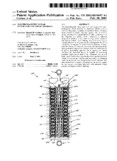
l|||||||||||||ll||l||||||||l|||||||||||||||||||||||l|||||||||||||||||||||||||||||||||||||| US 20030034697A1 (19) United States (12) Patent Application Publication (10) Pub. No.: US 2003/0034697 A1 Goldner et al. (43) Pub. Date: Feb. 20, 2003 (54) ELECTROMAGNETIC LINEAR (57) ABSTRACT GENERATOR AND SHOCK ABSORBER An electromagnetic linear generator and regenerative elec tromagnetic shock absorber is disclosed Which converts variable frequency, repetitive intermittent linear displace (76) Inventors: Ronald B. Goldner, Lexington, MA ment motion to useful electrical poWer. The innovative (US); Peter Zerigian, Arlington, MA device provides for superposition of radial components of (US) the magnetic ?ux density from a plurality of adjacent magnets to produce a maximum average radial magnetic ?ux density Within a coil Winding array. Due to the vector Correspondence Address: superposition of the magnetic ?elds and magnetic ?ux from R. Dennis Creehan, Esq, a plurality of magnets, a nearly four-fold increase in mag P_()_ BOX 750070 netic ?ux density is achieved over conventional electromag A?ington Heights, MA 02175-0070 (Us) netic generator designs With a potential sixteen-fold increase in poWer generating capacity. As a regenerative shock (21) App1_ NO_; 09/850,412 absorber, the disclosed device is capable of converting parasitic displacement motion and vibrations encountered (22) Filed; May 7, 2001 under normal urban driving conditions to a useful electrical energy for powering vehicles and accessories or charging Publication Classi?cation batteries in electric and fossil fuel poWered vehicles. The disclosed device is capable of high poWer generation capac (51) Int. Cl.7 .................................................. .. H02K 33/00 ity and energy conversion efficiency With minimal Weight (52) US. Cl. ............................................... .. 310/17; 310/15 penalty for improved fuel efficiency. M I00 Ffiiiill Patent Application Publication Feb. 20, 2003 Sheet 1 0f 15 US 2003/0034697 A1 // 3£.g5K5oE9gI72g?5a4n !3x’»!i i r.ntue1gimg1irii3tmeai </ |.. Jr _ l .nma. _“ : 0 w a _1 2.“? J-> gg~sig3ti-;du-g i gzaigadilraihmé ijw.; TN7fM“ “(HaC ? Patent Application Publication Feb. 20, 2003 Sheet 2 0f 15 US 2003/0034697 A1 \W. /_\/ j1 /\ 3mw2.13T.“5..J.5.;.:m.a.3 n ».5..;. newiw".3:I25wannml.l55n;.n3: ./3\ \a / ~\\1.\ // Em3ginmang?f? imwuba \//./\_m.: m_“3. /\ TUJ\Nu : m1\1w/m m\my ../ _i»i . . AM“; . Q/ M. N new G g.-gdi:gggk5logw2ubu nag 2Tq2ga.Iu.3:gi: .n g - ‘91am /\71W1 1 ! _... . nn — ~ w, Patent Application Publication Feb. 20, 2003 Sheet 3 0f 15 US 2003/0034697 A1 Patent Application Publication Feb. 20, 2003 Sheet 4 0f 15 US 2003/0034697 A1 Patent Application Publication Feb. 20, 2003 Sheet 5 0f 15 US 2003/0034697 A1 -t_- 11 == :. I? W ‘1 W 4 fr "WWW. ~~~~~~~ M“ 1 M Fig.5} \ 4 J - thumb.» in) ‘War Br Fig- 58 will!“ a‘ Q nun-comm an", (5) Patent Application Publication Feb. 20, 2003 Sheet 6 0f 15 US 2003/0034697 A1 ‘00 m O I80 to?“ A“ / (I Patent Application Publication Feb. 20, 2003 Sheet 7 of 15 US 2003/0034697 A1 a 3.5 a .. ‘f 3.0" .E‘ - 3 “ K C5 v .2 B *5 2.0“ r? _ as 1.5 a I. a g 1.0-» i a I .1‘. .5 0.5" 1: a .. 0o!!! i!llllltlll‘lllllllllll'll llllllllllllilljllilll! 12046-1244‘: 481216202428323640 Longitudinal position from one edge of magnet (mm) 2. (mm) Patent Application Publication Feb. 20, 2003 Sheet 8 0f 15 US 2003/0034697 A1 Patent Application Publication Feb. 20, 2003 Sheet 9 0f 15 US 2003/0034697 A1 M 3 (03 0 § [03’ mmI .1 F60 //// i 1m [Ol m ,/.1,r1, ,,.10.//.. 1 we
Description: