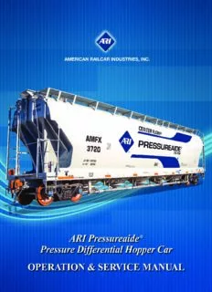
ARI PressureAide Manual PDF
Preview ARI PressureAide Manual
ARI Pressureaide®Car Table of Contents Introduction ..............................................................................................2 ARI Pressureaide®Car Models.................................................................3 Operating Equipment and Location For models PD3300, PD5001, PD5300 & PD5750.....................................6 Operating Instructions For models PD3300, PD5001, PD5300 & PD5750.....................................8 Operating Equipment and Location For model PD3720N...........................................................................12 Operating Instructions For model PD3720N...........................................................................14 Operating Equipment and Location For model PD5650N...........................................................................17 Operating Instructions For model PD5650N...........................................................................19 Standard Hatch Arrangement..................................................................22 Hatch Lever Adjustments........................................................................23 Cleaning..................................................................................................24 Requirements for Operating Air.............................................................27 Loading Operations.................................................................................28 Unloading Operations.............................................................................29 General Maintenance..............................................................................32 Trouble Shooting....................................................................................34 ARI Pressureaide®Car 2 Introduction The ARI Pressureaide®car is part of the ARI family of Centerflow®covered hopper cars. The Pressureaide®car is a pressure differential car, a self-contained transportation and unloading systemuniquely suited to handle a wide spectrum of fluidizable, dry bulk materialsranging from cement and flour to popcorn and peanuts. ARI’s Pressureaide®cars are equipped with all the required piping, operating valves and pressure relief devices necessary to operate the railcar. Upon arrival at the unloading site all that is required to unload is the connection of a product discharge hose and an air supply line. Available in six popular sizes, the model number corresponds to the cubic capacity of the car; PD3300, PD5001, PD5300,PD5750, PD3720N & PD5650N. Depending on the model, the Pressureaide®car has 3, 4 or 5 hoppers. All 3 and 4 hopper Pressureaide®car models have bulkheads between compartments. The PD3720N & PD5650N are exceptions with a clean boredesign without interior bulkheadsthat allow for “flood” loading of the entire car through a single hatch. Unloading of the car is accomplished using a process called fluidization. In the bottom of each compartment is a permeable membrane. Air is fed to the underside of the membranes then “bubbles” up through the product. Product particles become suspended in the “bubbles” of air and take on fluid-like properties. Once in suspension,the product flows from the car through the product discharge piping. The air also pressurizes the car and provides the energy to push or convey the product to the receiver. The Pressureaide®car can unload up to 100,000 pounds per hour at car body operating pressures up to 14.5 psig. Air flow and air quality are critical to the operation of the ARI Pressureaide®car. See “Requirements for Operating Air”on page 22 for detailed information. Contact American Railcar Industries, Inc. for assistance in operating the Pressureaide®car when using automated unloading systems as this presents a special set of circumstances. Compartment Identification The hoppers are identified using an alpha sequence beginning at the “B” end. “B” end = End of railcar with the handbrake. For a 5 hopper car the designations are B – BC – C – AC – A. For a 4 hopper car the designations are B – BC – AC – A. For a 3 hopper car the designations are B – C – A. ARI Pressureaide®Car Pressureaide® Car Models 3 PD3300 PD5001 ARI Pressureaide®Car 4 Pressureaide® Car Models PD5300 PD5750 ARI Pressureaide®Car Pressureaide® Car Models 5 PD3720N N denotes without bulkheads PD5650N N denotes without bulkheads ARI Pressureaide®Car 6 Operating Equipment and Location For models PD3300, PD5001, PD5300 & PD5750 PRODUCT VALVES 4 WAY AIR VALVES (one each hopper) (one each hopper) “A” “B” END END PRESSURE BY-PASS PRODUCT DISCHARGE AIR INLET BY-PASS GAUGE AIR VALVE CONNECTION (near side) AIR VALVE (one near side, one far side (far side-not shown) not shown) Note: Near side refers to the side of the car with the manifold piping. Far side refers to the side of the car opposite the manifold piping. ARI Pressureaide®Car Operating Equipment and Location 7 For models PD3300, PD5001, PD5300 & PD5750 CAR BODY VACUUM RELIEF SAFETY RELIEF RUPTURE DISC BLOWDOWN VALVE VALVE ASSEMBLY VALVE “A” “B” END END BLOWDOWN VALVE CHECK MANIFOLD CLEAN-OUT PORT CHECK HANDLE VALVE SAFETY RELIEF (one each hopper) VALVE VALVE ARI Pressureaide®Car 8 Operating Instructions For models PD3300, PD5001, PD5300 & PD5750 Unloading Controls 4-WAY Each compartment is AIR VALVE PRODUCT VALVE equipped with a product valve to regulate the flow of product entering the discharge manifold. A 4-way air valve controls the flow of air into each compartment. The valve operating positions are: Closed, Open Near Side, Open Far Side and Fully Open. An internal check valve is installed in the 4 position valve and prevents blowback in the event of a blower shut down. ARI Pressureaide®Car Operating Instructions 9 For models PD3300, PD5001, PD5300 & PD5750 A check valve and by-pass valve are BY-PASS AIR installed in series in the air supply CHECK VALVE VALVE line where the air supply connects to the discharge manifold. This arrangement permits conveying air to be metered into the discharge line. Blow Down Valve The car is equipped with a blow down valve to depressurize the car body. The valve is located on the “A” end of the car and is operated from ground level with a handle extension. The valve is closed when the handle position is parallel to the valve body. Note: This valve discharges air and dust at high velocity. Personnel must stand clear.
Description: