Arc Lamp Lighting Patents 18xx 2005 PDF
Preview Arc Lamp Lighting Patents 18xx 2005
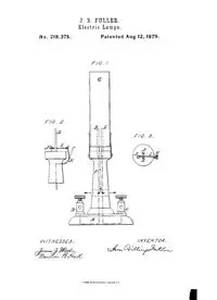
No. 218,375, J. B. PULLER. Eleotrio Lamps. PatentedAug t2, 1879. UNITED STAT S PATENT OFFICE. JI)[ BILLINGS FULLER~ OF NEW YORK, N. Y., ASSIGNOR~ BY)[ESNE ASSIGN- 5IENT, TO THE FULLED ELECTRICAL COSIPANY, OF NEW YOgi(. IMPROVEMENT IN ELECTRIC LAMPS. Specification ~rm~ng par~ of Letters Pa~en~ No. ~!S,~5, da~ed August 1~, 18~9; ~p~ica~on fi~d January 3~ 18~8. ~To all q~hom ~ ~a,y eoncer~ : Be it known that I, J~I BILLINGS ~ULLE~, of the ~ty of New York, State of New York, have invented a new and useful Improvement in Electric Lmnps, of which the tbllowing is a spedfica~on. This imwovement relates to electro lamps having carbons parallel lo each otherj and eon~sts, firsG in the employment of a current of air so directed as to flow around or be- tween sNd carbons and toward their lumi- nous pNnts, ~br the purpose of preven~ng O~e electric flame fl’om burning Nong the sat- thee of the carbons, where there is the least eleetNcal re~stane% and of keeping the flame at the points of the carbons j second~ in the pecMiar means employed tbr ex~ngNshing the light automatically, em~NsOng in connec- tions so arranged as to be bm’ned off, and the ~eetrie circuit with the lamp opened~ and the Neetric enn~nt interrupted by the action of the flame. There are many ways iu which a eurren~ of air may be applied in carrying out this inven- tion, depending on the eonstrue~on of the lamp and the postmen of the em’bm-ts. I em~Nder the manner herNn deseNbed the mesh practicable when the carbons are placed in a vertical poN~on, with the points upward. Figure 1 is a side view of the lamp. Figs. 2 and 3 are a side view and section of the de- vice ~br automatically extingnisMng the’ligh~ Iu the drawings~ A represents the base of an eleetNc lamp. The electro current fl~om the generator is conducted to the bin(ling’- posts B and C, and thence to the carbons D and E. These carbons are separated a short d~tanee apar~ and the electric current flows through the eleet~c are formed between fl~e points of said carbons. F is a tube arrangexl so as to give d~ee- fion ¢o a eurre~ of Nr around or between the carbons toward their luminous points. A ehimney~ G~ is arranged around sNd ear- bons~ so as to produce a draft of Nr from the heat of fl~e e]eetNe flame. When the carbons are used with the~ points downward, or in any po~on di~grent fl~om that above described, the air may be tbreed ~hrough the tube F by any convenient means; or m~y substitute for the tube may be used whiN~ will give the curren~ of air the necessary direeOon, as aforesNd. H is a sp~ng~ m~d I is a wire or metalhe st~p~ bo~] of which are in circuit with one of the earbou~ ~e wire b~ng arranged so as to be burned off by the flame at the dented poin~ . ~}~,~}~:~king the circuit and ex~nguish- There are many ways in which the circuit may be broken by bum~ing off a eonneeNon. A cord may pass between or around the ear- hens, hNding the eonnee~ng mechanism in dosed circuit until the bun~ing off of said cord by the ~ectric flame opens the Nrcnit and in- terrupts the eurr~,~ Therefore I do not con- fine mys~f to any particular mechanism tbr this purpose, prodded the curr~lt is inter- rupted by the means described. I am aware that glass globes have been iflaeed around the carbons of electric lamps ~br the purpose of soRcniug the light and pro- teeing it ~om ~e wind and storm. I elNm-- 1. An
